INTRODUCTION TO DESIGN (구조)설계의 대한 소개
Summary 요약
1.1 What is design? - Inputs, design process, scope of course.
1.2 Design
philosophy - permissible stress design, load factor method, limit state design.
1.1 What is design? 설계란 무엇인가?
The task of the structural engineer is to design
a structure which satisfies the needs of the client and the user. Specifically
the structure should be safe, economical to build and maintain, and aesthetically
pleasing. But what does the design process involve?
구조기술자가 해야할 일은 건축주와 사용자의 요구사항들을 만족시키는 구조물을
설계하는 것이다. 특히 그 구조물은 안전하고, 시공과 관리유지에 경제적이며, 미적으로
만족을 주어야 한다. 그러면 설계과정은 무엇을 포함하는가?
Design is a word that means different things
to different people. In dictionaries the word is described as a mental plan,
preliminary sketch, pattern, construction, plot or invention. Even amongst those
closely involved with the built environment there are considerable differences
in interpretation. Architects, for example, may interpret design as being the
production of drawings and models to show what a new building will actually
look like. To civil and structural engineers however, design is taken to mean
the entire planning process for a new building structure, bridge, tunnel, road
etc., from outline concepts and feasibility studies through mathematical calculations
to working drawings which could show every last nut and bolt in the project.
Together with the drawings there will be bills of quantities, a specification,
and a Contract, which will form the necessary legal and organisation framework
within which a contractor, under the supervision of engineers and architects,
can construct the scheme.
설계라는 말은 각기 다른 사람에게 서로 다른 것을 의미하는 단어이다. 사전 상에는
설계란 단어는 일차적으로는 스케치, 패턴, 시공, 구성이나 발명과 같은 정신상의
계획으로 기술되어 있다. 심지어 건설환경과 아주 가깝게 연관된 부분들에도 조차도
그 번역에 있어서 상당한 차이가 있다. 예컨데, 건축가는 설계란 말을 새로운 건물이
실제로 보여지는 것을 가시화시키는 도면이나 모델을 만드는 것으로 해석할 것이다.
그러나 시공기술자나 구조기술자에게 있어서는 새로운 구조물, 교량, 터널, 도로
등의 대략적인 개념이나 수학적 계산을 통한 타당성 조사에서부터 그 프로젝트의
모든 최후의 너트와 볼트를 보여주는 시공도에 이르기까지의 전체적인 계획과정을
의미한다. 도면과 같이 기술자나 건축가의 관리하에 도급자가 계획을 세우는 필요한
법률상의 그리고 조직상의 체계를 구성하는 수량계산서, 규준, 그리고 계약서를 의미할
수도 있다.
There are many inputs into the engineering design
process as illustrated by Figure 1.1 including
다음과 같이 그림1.1에서 보여지듯이 공학적인 설계과정에 들어가는 많은 인자들이
있다.
(a) Client brief 건축주의 요구사항
(b)
Experience 경험
(c) Imagination 상상력
(d) A site investigation 현장
조사
(e) Model and laboratory tests 모델을 통해 그리고 실험실에서 이루어지는
테스트
(f) Economic factors 경제적 요인들
(g) Environmental factors
환경적 요인들
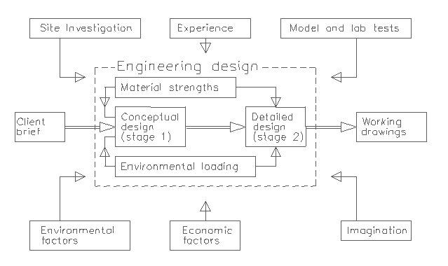
Figure 1.1 - Inputs into
the design process 설계과정에 포함되는 인자들
The starting point for the designer is normally
a conceptual brief from the client, who may be a private developer or perhaps
a government body. The conceptual brief may simply consist of some sketches
prepared by the client or perhaps a detailed set of architects drawings.
설계자의 출발점은 일반적으로 민간개발업자나 아마도 정부기관이 될 수도 있는 건축주로부터의
개념적인 요구사항들이다. 개념적인 요구사항은 단순히 건축주에 의해 준비된 약간의
스케치나 혹은 건축도면들로 단순히 구성된다.
Experience is crucially important, and a client
will always demand that the firm he is employing to do the design has previous
experience designing similar structures.
경험은 매우 중요하며, 건축주는 항상 설계를 하기위해 고용하고 있는 회사가 자신이
생각하고 있는 구조물과 유사한 구조물들을 이전에 경험해 본 적이 있는지를 요구하기
마련이다.
Although imagination is thought by some to be
entirely the domain of the architect, this is not so. For engineers and technicians
an imagination of how elements of structure inter-relate in three dimensions
is essential, as is an appreciation of the loadings to which structures might
be subject in certain circumstances. In addition, imaginative solutions to engineering
problems are often required to save money, time, or to improve safety or quality.
비록 상상력이 일부 사람들에 의해 전적으로 건축가의 영역이라고 생각되어질지라도,
실은 그렇지 않다. 공학자나 기술자들에게 있어서 구조물의 구성요소들이 어떻게
삼차원적으로 상호관계를 가지는가에 대한 상상력은 필수적이다. 구조물이 어떤 일정한
환경 아래서 주어지는 하중을 평가하는 것도 마찬가지이다. 게다가, 공학적 문제에
대한 상상력이 풍부한 해결안은 종종 돈, 시간을 절약하거나 안전성이나 품질을 향상시키기
위해 요구되어진다.
A site investigation is essential to determine
the strength and other characteristics of the ground on which the structure
will be founded. If the structure is unusual in any way, or subject to unusual
loadings, model or laboratory tests may also be used to help determine how the
structure will behave.
현장조사는 구조물이 서게될 지반의 강도와 다른 특성들을 결정하기 위해서 필수적인
부분이다. 어떠한 이유로해서 구조물이 특수한 것이거나 특수한 하중을 받는 경우라면,
모델을 통하거나 실험실에서의 테스트도 구조물이 어떻게 거동할 것인지를 결정하는데
도움을 주기 때문에 사용되어진다.
In today's economic climate a structural designer
must be constantly aware of the economic implications of his or her design.
On the one hand design should aim to achieve economy of materials in the structure,
but over-refinement can lead to an excessive number of different sizes and components
in the structure, and labour costs will rise. In addition the actual cost of
the designers time should not be excessive, or this will undermine the employers
competitiveness. The idea is to produce a workable design achieving reasonable
economy of materials, while keeping manufacturing and construction costs down,
and avoiding unnecessary design and research expenditure.
오늘날의 경제적인 환경에서 구조기술자는 자기자신의 설계가 지니는 경제적인 함의를
항상 의식하고 있어야만 한다. 반면에 설계는 구조물에서 재료의 경제성을 획득하기
위해 초점이 맞추어져야 하지만, 지나치게 정제된 설계를 할 경우 구조물에서 지나치게
많은 규격과 부재들을 필요로 하게 되어 노무비가 커질 것이다. 설계자의 실제 비용뿐만아니라
시간도 지나치게 많으면 안되며, 그럴경우 경쟁성에서 뒤떨어지기 마련이다. 결론은
제작비용과 시공비용을 줄이고, 불필요한 설계와 연구노력을 피하면서도 합리적인
재료상의 경제성을 지닌 시공가능한 설계를 만들어내는 것이다.
Designers must also understand how the structure
will fit into the environment for which it is designed. Today many proposals
for engineering structures stand or fall on this basis, so it is part of the
designers job to try to anticipate and reconcile the environmental priorities
of the public and government.
설계자는 또한 구조물이 그 안에서 설계되어지는 환경에 어떻게 잘 들어맞는지를
이해해야만 한다. 오늘날 많은 공학적 구조물들에 대한 제안들이 이런 사항이 근거를
두고 수락되기도 하고 거절되기도 한다. 따라서 공공 대중과 정부의 환경상의 우선권을
예측하고 이에 타협점을 찾아내도록 노력하는 것이 설계자의 업무의 한 부분이다.
The engineering design process can often be
divided into two stages:
(1) a feasibility study involving a comparison of the alternative forms of structure,
and selection of the most suitable type and
(2) a detailed design of the
chosen structure.
공학상의 설계과정은 종종 크게 두 단계로 나뉘어질 수 있다 :
(1) 구조물의
다른 대안들과의 비교를 통한 타당성조사와 그에 따른 가장 적합한 유형의 선택
(2) 선택된 구조물에 대한 상세설계
The success of stage 1, the conceptual design,
relies to a large extent on engineering judgement and instinct, both of which
are the outcome of many years experience of designing structures. Stage 2, the
detailed structural design, also requires these attributes but is usually more
dependent upon a thorough understanding of the codes of practice for structural
design, eg. BS8110 and BS5950. These documents are based on the amassed experience
of many generations of engineers, and the results of research. They help to
ensure safety and economy of construction, and that mistakes are not repeated.
For instance, after the infamous disaster at the Ronan Point block of flats
in Newham, London, when a gas explosion caused a serious partial collapse, research
work was carried out, and codes of practice were amended so that such structures
could survive such a gas explosion, with damage being confined to one level.
1단계인 개념적 설계의 성공은 공학적 판단과 본능에 매우 크게 의존하는데, 이 둘
모두 구조물을 설계한 수십년간의 경험의 산출물이다. 2단계인 상세 구조설계도 또한
이런 면들을 요구하지만, 일반적으로 BS8110이나 BS5950과 같은 구조설계에 대한
실무 규준에 대한 깊이있는 이해에 더욱 의존한다. 이런 문서들은 수세대에 걸친
기술자들의 축적된 경험에 기초하고 있으며, 연구의 결과물들이다. 또한 시공의 안전성과
경제성을 확신하는데 도움을 주며, 실수들이 반복되지 않게 된다. 예를 들면, 런던
뉴햄에서 있었던 가스폭발이 심각한 부분적인 붕괴를 야기한 Ronan Point 블럭의
아파트에서 일어난 악명높은 재해 이후에 연구작업이 수행되었고, 실무규준들이 구조물이
그러한 가스폭발 아래서도 붕괴되지 않고 손상이 한 층에만 국한되도록 재수정되었다.
1.2 Design Philosophy 설계철학
Table 1.1 illustrates some risk
factors that are associated with activities in which people engage. It can be
seen that some degree of risk is associated with air and road travel. However
people normally accept that the benefits of mobility outweigh the risks. Staying
in buildings, however, has always been regarded as fairly safe. The risk of
death or injury due to structural failure is extremely low, but as we spend
most of our life in buildings this is perhaps just as well.
표 1.1은 인간이 영위하는 행위에 관련된 일종의 위험요인을 보여준다. 어느 정도의
위험이 항공여행과 도로여행에 관련되어 있음이 보여진다. 그러나 사람들은 통상적으로
운송기능의 이점이 위험요인을 능가한다고 인정한다. 그러나 건물에 머물러있는 것은
항상 매우 안전하다고 여겨져왔다. 구조물의 파괴로 인한 죽음이나 부상의 위험은
매우 낮지만, 우리가 우리 인생의 대부분의 시간을 건물에서 보내기 때문에 이런
경우도 아마 마찬가지이다.
Mountaineering (International) 등산(국제적)
2700
Air Travel (International) 항공여행(국제적)
120
Deep Water Trawling 심해트롤어업 59
Car Travel 자동차 여행 56
Coal Mining 탄광작업
21
Construction Sites 건설현장 8
Manufacturing 제조업 2
Accidents at Home 집안사고
2
Fire at Home 집안화재 0.1
Structural Failures 구조물 붕괴 0.002
Table 1.1 - Comparative Death
Risk per 108 Persons Exposed
표 1.1 - 노출된 108명의 사람들에 대한 비교 사망 위험
As far as the design of structures for safety is concerned, it is seen as the
process of ensuring that stresses due to loading at all critical points in a
structure have a very low chance of exceeding the strength of materials used
at these critical points. Figure 1.2 illustrates this in statistical terms.
안전에 대해서 구조설계가 관계되는 한, 구조설계는 구조물에 있는 모든 위험부위들(critical
points의 번역)에서 받는 하중으로 인한 응력이 그 부분들에 사용된 재료의 강도를
초과할 확률이 매우 낮아야만 한다. 그림 1.2는 통계적인 측면에서 이런 점을 나타낸다.
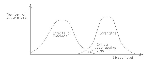
Figure 1.2 - Relationship
between stress and strength 응력과 강도의 관계
In design there exist within the
structure a number of critical points (eg beam midspans) where the design process
is concentrated. The normal distribution curve on the left of Figure 1.2 represents
the actual maximum material stresses at these critical points due to the loading.
Because loading varies according to occupancy and environmental conditions,
and because design is an imperfect process, the material stresses will vary
about a modal value - the peak of the curve. Similarly the normal distribution
curve on the right represents material strengths at these critical points, which
are also not constant due to the variability of manufacturing conditions.
설계에는 구조물 자체에 설계과정이 집중되어지는 많은 위험부위들(예컨데, 보의
가운데 스팬)이 존재한다. 그림 1.2의 왼쪽에 있는 정규분포곡선은 하중에 기인한
이런 위험부위들에서의 실제로 재료에 생기는 최대응력을 나타낸다. 하중은 사람의
구조물에서의 활동과 환경적 조건에 따라서 변하며, 설계란 불완전한 하나의 과정이기
때문에, 재료에 생기는 응력은 곡선의 가운데가 높은 모달값을 중심으로 변화한다.
이와유사하게 오른쪽의 정규분포곡선은 이런 위험부위들에서의 재료의 강도를 나타내는데,
제조 조건의 변동성에 기인해 일정한 값을 갖지 않는다.
The overlap between the two curves represents
a possibility that failure may take place at one of the critical points, as
stress due to loading exceeds the strength of the material. In order for the
structure to be safe the overlapping area must be kept to a minimum. The degree
of overlap between the two curves can be minimised using one of three distinct
design philosophies, namely
이 두 곡선이 겹친부위는 그런 위험부위들 중의 한 곳에서 파괴가 일어날 확률을
나타내는데, 이는 하중으로 인한 응력이 재료의 강도보다 클 경우에 발생한다. 구조물이
안전하기 위해서는 이 겹친 부분의 넓이가 최소가 되도록 유지되어야만 한다. 두
곡선 사이의 겹친 정도는 세 가지의 서로 다른 설계철학들 중의 한 가지를 사용함으로써
최소화되어질 수 있다, 즉
(a) permissible stress design 허용응력설계
(b) load factor method 하중계수방법
(c) limit state design 한계상태설계
1.2.1 Permissible Stress Design 허용응력설계
In permissible stress design, sometimes referred to as modular ratio or elastic
design, the stresses in the structure at working loads are not allowed to exceed
a certain proportion of the yield stress of the construction material, ie. the
stress levels are limited to the elastic range. By assuming that the stress-strain
relationship over this range is linear, it is possible to calculate the actual
stresses in the material concerned. Such an approach formed the basis of the
design methods used by CP114 (the forerunner of BS8110), and BS449 (the forerunner
of BS5950).
종종 모듈러비나 탄성설계라고 불리는 허용응력설계에서는 사용하중을 받는 구조물의
응력이 시공재료의 항복응력의 일정 비율치를 초과해서는 안된다, 즉 응력 수준이
탄성범위에 제한된다. 이런 범위에서는 응력-변형도 관계가 선형이라고 가정함으로써,
관계된 재료에 생기는 실제 응력을 계산하는 것이 가능하다. 이런 접근법이 CP114(BS8110의
선구자적인 규준)나 BS449에 의해 사용된 설계방법의 근간을 이루었다.
However this philosophy had two major drawbacks. Firstly permissible design
methods sometimes tended to over-complicate the design process and also lead
to conservative solutions. Secondly, as the quality of materials increased and
the safety margins decreased, the assumption that the stress-strain curve was
linear became unjustifiable for materials such as concrete, making it impossible
to estimate the true factors of safety.
그러나 이런 설계철학은 두 가지 중요한 취약점을 가진다. 먼저 허용설계법은 종종
설계과정을 지나치게 복잡하게 하는 경향이 있으며 또한 너무 보수적인(지나치게
안전측으로) 해결안을 내놓는 경향이 있다. 다음으로는 재료의 품질이 향상되고 안전율이
줄어듦에 따라, 응력-변형도 관계가 직선이라는 가정이 콘크리트와 같은 재료에 있어서는
정당화되지 못하게 됨으로써, 실제 안전율을 측정하는 것이 불가능하게 된다.
1.2.2 Load Factor Design 하중계수설계
Load factor or plastic design was developed to take account of the behaviour
of the structure once the yield point of the construction material had been
reached. This approach involved calculating the collapse load of the structure.
The working load was derived by dividing the collapse load by a load factor.
하중계수설계 혹은 소성설계는 시공재료가 항복점에 도달했을 때의 구조물의 거동을
고려하기 위해서 개발되었다. 이 접근법은 구조물의 파괴하중을 계산하는 과정을
포함한다. 사용하중은 파괴하중을 하중계수로 나눔으로써 알 수 있다.
This approach simplified methods of analysis and allowed actual factors of safety
to be calculated. It was in fact permitted in CP114 and BS449 but was slow in
gaining acceptance and was soon superseded by the more comprehensive limit state
approach.
이 접근법은 해석방법을 간단하게 했으며 실제의 안전율을 계산하는 것을 가능케
하였다. 소성설계는 CP114와 BS449에서 실제로 허용되었으나 일반적인 인정을 얻는데는
아직 미흡하며 더욱 정교한 극한상태 접근법에 의해 곧 그 빛이 바래졌다.
The difference between these two approaches is illustrated below.
이 두 접근법의 차이점이 아래에 예시되어있다.
Example 1.1 - Comparison of Approaches to
Design 설계접근법들의 비교
Consider the case of a solid rectangular beam, b wide by d deep, with a span
of 10 metres. In example (a) the beam is simply supported, and in example (b)
it is built in at each end. Assuming a safety factor of 1.5 calculate the minimum
width of beam using permissible stress and load factor approaches.
폭이 b이고 춤이 d이며, 스팬이 10m인 직사각형 보가 12kN/m의 등분포하중을 받고
있는 경우를 생각해보자. 예컨데, (a) 보는 단순지지되어 있으며, (b) 보의 양단에서
지지되고 있다. 1.5의 안전율을 고려해서 허용응력설계와 하중계수설계를 사용하여
보의 최소폭을 계산하라.
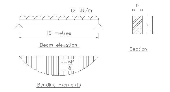
Figure 1.3 - Simply supported
beam 단순지지보
Permissible stress approach 허용응력설계법
M = W*l*l/8 = 12(kN/m)*10(m)*10(m)/8=150 (kNm)
S perm = S ult/1.5
Elastic beam theory gives 탄성 보이론은 다음과 같다.
Mc = S perm*Z
150 = (S ult/1.5)*(bd2/6)
b = 1350/(S ult*d2)
Load factor approach 하중계수설계법
계수하중 = 12 x 1.5 = 18 kN/m
M = W*l*l/8 = 18(kN/m)*10(m)*10(m)/8=225 (kNm)
Plastic beam theory gives 소성 보이론은 다음과 같다.
Mc = S ult*S
225 = S ult*(bd2/4)
b = 900/(S ult*d2)
여기서,
S perm = Permissible stress 허용응력;
S ult = Ultimate
or failure stress 극한응력 혹은 파괴응력;
M = Effective bending moment 유효휨모멘트;
Mc = Moment capacity 모멘트 커패시티;
S = Plastic section modulus 소성단면계수;
Z = Elastic section modulus 탄성단면계수
For the special case of a rectangular beam it
can be seen that the permissible stress method gives a relatively conservative
solution compared with the load factor method, although the same safety factor
is used. However the permissible stress method does model behaviour under working
loads, and realistic predictions of behaviour in service can be calculated.
The load factor method only models failure, however, and no information on behaviour
in service can be obtained.
직사각형보의 특수한 경우에는 비록 같은 안전율이
사용되더라도, 허용응력설계가 하중계수설계법에 비해서 상대적으로 보수적인 해결안을
산출한다. 그러나 허용하중설계는 사용하중을 받을 때의 거동을 모델화한 것이기
때문에 사용하중을 받는 구조물의 거동을 현실적으로 예측하여 계산할 수 있다. 그러나
하중계수설계는 단지 파괴를 모델화한 것이기 때문에 사용하중을 받을 때의 거동에
대해서는 아무런 정보도 주지 못한다.
1.2.3 Limit state design 한계상태설계
Originally formulated in Russia in the 1930's and
developed in Europe in the 1960's, limit state design can perhaps be seen as
a compromise between the permissible stress and load factor methods. It is in
fact a more comprehensive approach which takes into account both methods in
appropriate ways. Most modern structural codes of practice are now based on
a limit state approach. BS8110 for concrete, BS5950 for structural steelwork,
BS5400 for bridges, and BS5628 for masonry are all limit state codes. The principal
exceptions are the code of practice for design in timber, BS5268, and the old
(but still current) structural steelwork code, BS449, both of which are permissible
stress codes.
1930년대에 러시아에서 최초로 고안되었으며
1960년대에 유럽에서 발전된 한계상태설계는 허용응력설계와 하중계수설계 사이의
일종의 타협점으로 볼 수 있다. 사실 한계상태설계는 적당한 방식으로 두 가지 설계법을
모두 고려한 좀더 세련된 접근법이다. 현재 사용되고 있는 대부분의 구조설계규준들은
극한상태설계에 기초를 두고 있다. 콘크리트에 대해서는 BS8110, 철골에 대해서는
BS5950, 교량에 대해서는 BS5400, 조적조에 대해서는 BS5628이 사용되고 있는데 이들이
모두 극한상태설계에 근거한 규준들이다. 목구조 설계규준으로 사용되는 BS5268와
철골조에 사용되는 BS449에는 예외적으로 한계상태설계가 적용되지 않고 허용응력설계에
근거한 규준이 사용된다.
Two limit states are examined. 두 개의 한계상태는
다음과 같다.
(a)
Ultimate limit state 극한한계상태
Similar to load factor design, failure of the structure
is "modelled" with appropriate safety factors on loading. In addition
partial safety factors are also applied to material strengths. The ultimate
limit state is concerned with the maximum load-carrying capacity of the structure
and plastic analysis methods are appropriate, if they can be applied.
하중계수설계와 유사하게 구조물의 파괴는 하중에
대한 적절한 안전율을 가지고 모델화된다. 또한 부분적인 안전율이 재료의 강도에도
적용된다. 극한한계상태는 구조물의 최대 하중지지능력과 관계되며 소성해석법이
적용될 수 있다면 적절하다.
(b)
Serviceability limit state 사용성한계상태
The serviceability limit state is concerned with
certain aspects of the structure at working loads, in particular deflection
and cracking. Normally behaviour of members at serviceability limit state is
elastic.
사용성한계상태는 사용하중을 받는 구조물의 특성에
관계되는데, 특히 휨이나 균열이 생기는 경우가 그렇다. 일반적으로 사용성한계상태에
있는 부재의 거동은 탄성이다.
As this approach forms the basis of the design
methods in most modern codes of practice for structural design, it is essential
that the design methodology is fully understood.
이런 접근법은 구조설계에 대한 대부분의 현대적인
실제 규준들의 근간을 이루기 때문에, 설계방법론에 대한 완벽한 이해는 필수불가결하다.
1.2.3.1
Characteristic and design values 특성과 설계값들
As stated at the outset, when checking whether
a particular member is safe, the designer cannot be certain about either the
strength of the material composing the member or, indeed, the load which the
member must carry. The material strength may be less than intended
위에서 개략적으로 말했듯이, 어떤 부재가 안전한지를
확인할 때, 설계자는 부재를 구성하는 재료의 강도와 실제 부재가 지지하는 하중의
그 어느 것에 대해서도 확신을 할 수가 없다. 재료강도는 예상했던 것보다 작을 수도
있는데,
(a) because of it's variable composition,
and
(a) 재료 구성상의 변동성 때문에
그러하며,
(b) because of the variability of manufacturing
conditions during construction, and other effects such as corrosion.
(b) 시공하는 동안 제조조건의 변동성과 부식과 같은 다른
요인들 때문에 그러하다.
Similarly the load in the member may be greater
than anticipated
마찬가지로 부재가 지지하는 하중도 예측했던 것보다
더 클 수가 있는데,
(a) because of the variability of the occupancy
or environmental loading, and
(a) 사용자의
거주상태와 주위 하중의 변동성 때문에 그러하며,
(b) because of unforeseen circumstances which
may lead to an increase in the general level of loading, errors in the analysis,
errors during construction etc.
(b)
일반적 수준의 하중을 초과할 수 있는 예측치 못한 환경요인, 해석상의 실수, 시공중의
오차 등 때문에 그러하다.
In each case, item (a) is allowed for by using
a characteristic value. The characteristic strength is the value below which
the strength lies in only a small number of cases. Similarly the characteristic
load is the value above which the load lies in only a small percentage of cases.
In the case of strength the characteristic value is determined from test results
using statistical principles, and is normally defined as the value below which
not more than 5% of the test results fall. However, at this stage there is insufficient
data available to apply statistical principles to loads. Therefore the characteristic
loads are normally taken to be the design loads from previous codes of practice.
각각의 경우에, (a) 사항은 특성치를 사용함으로써
고려될 수 있다. 일반적으로 강도는 매우 적은 경우에 특성강도보다 작게 된다. 마찬가지로
일반적으로 하중은 매우 적은 확률을 가지고서 특성하중보다 크게 된다. 강도의 경우에
특성치는 통계학적인 원리를 이용한 실험결과로부터 결정이 되며, 일반적으로 실험결과치가
특성치보다 낮은 확률이 5%보다 낮게 된다. 그러나 이 단계에서 통계학적인 원리를
하중에 적용하기에 불충분한 점이 있다. 따라서 특성하중은 일반적으로 이전 규준들에서
사용된 설계하중을 취한다.
Thus the characteristic dead load (Gk), which
represents the weight of the structure including finishes, fixtures and partitions,
can be estimated using BS648: Schedule of Weights for Building Materials and
BS6399: Design Loads for Buildings, Part 1: Code of Practice for Dead and Imposed
Loads. Similarly typical design values of the characteristic imposed load (Qk),
which represents the load due to the proposed occupancy, are given in BS6399.
The characteristic wind loads (Wk) are obtained using BS6399 Part 3, formerly
CP3: Chapter 5: Part 2.
따라서 마감재, 벽체부착물, 비내력벽을 포함하는
구조물의 무게를 나타내는 특성고정하중은 다음의 규준들을 이용해서 추정할 수 있다
: BS648: Schedule of Weights for Building Materials and BS6399: Design Loads
for Buildings, Part 1: Code of Practice for Dead and Imposed Loads. 마찬가지로,
가정한 거주성에 기인한 하중을 나타내는 특성치를 포함한 하중의 설계치는 BS6399에서
구할 수 있다. 특성풍하중은 다음 규준을 이용해서 구할 수 있다 : BS6399 Part 3,
formerly CP3: Chapter 5: Part 2
The overall effect of items under (a) and
(b) is allowed for using a partial safety factor, gm for strength, gf for load.
The design strength is obtained by dividing the characteristic strength by the
partial safety factor for strength
(a)와 (b)에 해당하는 항목들의 전체적인 영향은
부분안전율을 사용함으로써 고려할 수 있다. 강도에 대해서는 gm을, 하중에 대해서는
gf를 사용한다. 설계강도는 특성강도를 강도에 대한 부분안전율gm로 나눔으로써 얻어질
수 있다.
ie design strength = characteristic
strength/gm
설계강도 = 특성강도/부분안전율
The choice of values for gm depend on the material
being considered. For instance, the strength of in-situ concrete is more likely
to be affected by the nature of the construction process than the strength of
the reinforcing steel. This is accounted for in limit state design by assigning
a higher factor of safety to concrete (1.5) than reinforcing steel (1.15).
강도에 대한 부분안전율 gm의 값을 선택하는 것은
고려되는 재료에 달려있다. 예컨데, 현장타설 콘크리트의 강도는 철근의 강도보다
시공과정의 성격에 의해 더 큰 영향을 받기 마련이다. 한계상태설계에서는 이런 현상을
철근에 사용되는 1.15의 안전율보다 콘크리트에서 더 큰 1.5란 안전율을 사용함으로서
해결한다.
The design load is obtained by multiplying the
characteristic load by the partial safety factor for load
설계하중은 특성강도에 하중에 대한 부분안전율을
곱함으로써 얻을 수 있다.
ie design load = characteristic
load x gf
설계하중 = 특성하중 x 부분안전율
The value for gf depends on several factors
including the limit state under consideration and the accuracy of predicting
the loads on the structure. For instance, at the ultimate limit state dead loads
are multiplied by 1.4 and imposed loads by 1.6. However at the serviceability
limit state these factors reduce to 1.0.
하중에 대한 부분안전율의 값은 고려하는 한계상태와
구조물에 작용하는 하중예측의 정확성을 포함하는 여러 요인들에 근거해 결정된다.
예컨데, 극한한계상태에서는 고정하중은 1.4란 부분안전율을 곱하고 이동하중에 대해서는
1.6을 곱한다. 그러나 사용성 극한 상태에서는 이 값들이 모두 1.0이 된다.
In general, once a preliminary assessment of the
design loads has been made it is then possible to calculate the maximum bending
moments, shear forces and deflections in the structure.
일반적으로 일단 설계하중에 대한 초기 평가가 이루어지면,
구조물의 최대 휨모멘트와 전단력, 그리고 휨을 계산하는 것이 가능하다.
The construction material must be capable
of withstanding these forces otherwise failure of the structure may occur. Simplified
procedures for calculating the moment, shear and axial capacities of the members
together with acceptable deflection limits are described in the appropriate
codes of practice. These allow the designer to rapidly assess the suitability
of the proposed elements of structure. The aim of the following lectures then
is to discuss these procedures in respect of reinforced concrete, steelwork
masonry and timber structures.
시공재료는 이런 힘들을 지탱할 수 있어야만 하며
그렇지 않을 경우 구조물은 파괴된다. 수용할 만한 휨한계치를 만족시키면서 부재의
모멘트, 전단력, 그리고 축력을 계산하는 단순화된 과정은 적절한 규준을 찾아보면
기술되어 있다. 이는 설계자로 하여금 제안된 구조물 부재의 적합성을 빨리 평가할
수 있도록 해준다. 다음에 이러지는 강의의 목적은 이런 과정들을 철근콘크리트,
철골조, 조적조, 그리고 목조의 측면에서 토의하는 것이다.
원문보기